- 您现在的位置:买卖IC网 > Sheet目录17367 > ISL85033EVAL2Z (Intersil)EVAL BOARD2 FOR ISL85033
ISL85033
condition has cleared. If the overcurrent fault counter overflows
during soft-start, the converter shuts down and this hiccup mode
operation repeats.
Thermal Overload Protection
Thermal overload protection limits maximum junction
temperature in the ISL85033. When the junction temperature
(T J ) exceeds +150°C, a thermal sensor sends a signal to the fault
monitor.
The fault monitor commands the buck regulator to shut down.
When the junction temperature has decreased by 20°C, the
regulator will attempt a normal soft-start sequence and return to
Synchronization Control
The frequency of operation can be synchronized up to 2MHz by
an external signal applied to the SYNCIN pin. The falling edge on
the SYNCIN triggers the rising edge of PHASE1/2. The switching
frequency for each output is half of the SYNCIN frequency.
Output Inductor Selection
The inductor value determines the converter’s ripple current.
Choosing an inductor current requires a somewhat arbitrary
choice of ripple current, Δ I. A reasonable starting point is 30% of
total load current. The inductor value can then be calculated
using Equation 5:
V IN – V OUT V OUT
Fs × Δ I
normal operation. For continuous operation, the +125°C
junction temperature rating should not be exceeded.
L = ---------------------------- × -------------
V IN
(EQ. 5)
BOOT Undervoltage Protection
If the BOOT capacitor voltage falls below 2.5V, the BOOT
undervoltage protection circuit will pull the phase pin low through
a 1 ? switch for 400ns to recharge the capacitor. This operation
may arise during long periods of no switching as in no load
situations.
Application Guidelines
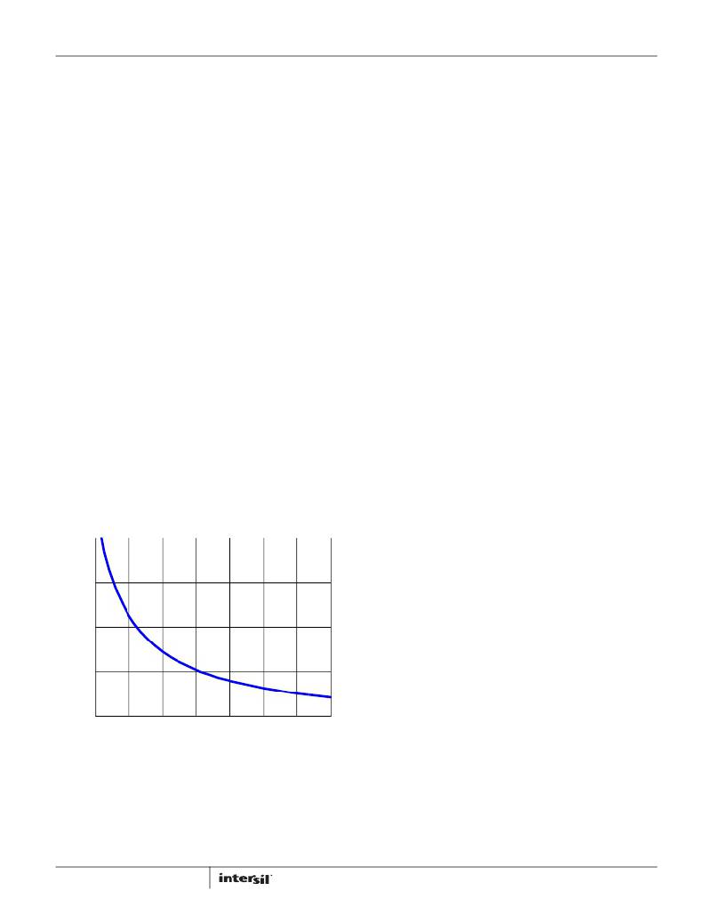
Operating Frequency
The ISL85033 operates at a default switching frequency of
500kHz if FS is tied to VCC. Tie a resistor from FS to GND to
program the switching frequency from 300kHz to 2MHz, as
Increasing the value of inductance reduces the ripple current and
thus ripple voltage. However, the larger inductance value may
reduce the converter’s response time to a load transient. The
inductor current rating should be such that it will not saturate in
overcurrent conditions.
Buck Regulator Output Capacitor Selection
An output capacitor is required to filter the inductor current.
Output ripple voltage and transient response are 2 critical factors
when considering output capacitance choice. The current mode
control loop allows the usage of low ESR ceramic capacitors and
thus smaller board layout. Electrolytic and polymer capacitors
may also be used.
shown in Equation 4.
R FS [ k Ω ] = 122k Ω? ( t – 0.17 μ s )
Where:
t is the switching period in μs.
300
200
100
(EQ. 4)
Additional consideration applies to ceramic capacitors. While
they offer excellent overall performance and reliability, the actual
in-circuit capacitance must be considered. Ceramic capacitors
are rated using large peak-to-peak voltage swings and with no DC
bias. In the DC/DC converter application, these conditions do not
reflect reality. As a result, the actual capacitance may be
considerably lower than the advertised value. Consult the
manufacturers data sheet to determine the actual in-application
capacitance. Most manufacturers publish capacitance vs DC bias
so that this effect can be easily accommodated. The effects of
AC voltage are not frequently published, but an assumption of
~20% further reduction will generally suffice. The result of these
considerations can easily result in an effective capacitance 50%
lower than the rated value. Nonetheless, they are a very good
choice in many applications due to their reliability and extremely
low ESR.
The following equations allow calculation of the required
capacitance to meet a desired ripple voltage level. Additional
capacitance may be used.
V OUTripple = -----------------------------------
0
500 750 1000 1250 1500
FS (kHz)
FIGURE 43. R FS SELECTION vs FS
1750
2000
For the ceramic capacitors (low ESR): =
Δ I
8 ? F SW ? C OUT
(EQ. 6)
where Δ I is the inductor’s peak to peak ripple current, F SW is the
switching frequency and C OUT is the output capacitor.
If using electrolytic capacitors then:
18
V OUTripple = Δ I*ESR
(EQ. 7)
FN6676.6
February 23, 2012
发布紧急采购,3分钟左右您将得到回复。
相关PDF资料
MIC5891BWM
IC DRVR LATCH 8BIT SER IN 16SOIC
MIC5891BN
IC DRVR LATCH 8BIT SER IN 16DIP
TAAB336K010G
CAP TANT 33UF 10V 10% AXIAL
SPX385AS-L-1-2
IC VREF SHUNT PREC 1.235V 8SOICN
A9AAT-1105F
FLEX CABLE - AFE11T/AF11/AFE11T
TDC225K025NSE
CAP TANT 2.2UF 25V 10% RADIAL
MIC5841BWM TR
IC DRVR LATCH 8BIT SER IN 18SOIC
SPX432AM-L
IC VREF SHUNT PREC ADJ SOT-23-3
相关代理商/技术参数
ISL85033IRTZ
功能描述:IC REG BUCK SYNC ADJ 3A 28TQFN RoHS:是 类别:集成电路 (IC) >> PMIC - 稳压器 - DC DC 开关稳压器 系列:- 产品培训模块:Lead (SnPb) Finish for COTS
Obsolescence Mitigation Program 标准包装:2,500 系列:- 类型:降压(降压) 输出类型:两者兼有 输出数:1 输出电压:5V,1 V ~ 10 V 输入电压:3.5 V ~ 28 V PWM 型:电流模式 频率 - 开关:220kHz ~ 1MHz 电流 - 输出:600mA 同步整流器:无 工作温度:-40°C ~ 125°C 安装类型:表面贴装 封装/外壳:16-SSOP(0.154",3.90mm 宽) 包装:带卷 (TR) 供应商设备封装:16-QSOP
ISL85033IRTZ-T
功能描述:IC REG BUCK SYNC ADJ 3A 28TQFN RoHS:是 类别:集成电路 (IC) >> PMIC - 稳压器 - DC DC 开关稳压器 系列:- 产品培训模块:Lead (SnPb) Finish for COTS
Obsolescence Mitigation Program 标准包装:2,500 系列:- 类型:降压(降压) 输出类型:两者兼有 输出数:1 输出电压:5V,1 V ~ 10 V 输入电压:3.5 V ~ 28 V PWM 型:电流模式 频率 - 开关:220kHz ~ 1MHz 电流 - 输出:600mA 同步整流器:无 工作温度:-40°C ~ 125°C 安装类型:表面贴装 封装/外壳:16-SSOP(0.154",3.90mm 宽) 包装:带卷 (TR) 供应商设备封装:16-QSOP
ISL85033IRTZ-T7A
功能描述:直流/直流开关调节器 3A STD BUCK REG - 4X 4 TQFN 250 PC REEL RoHS:否 制造商:International Rectifier 最大输入电压:21 V 开关频率:1.5 MHz 输出电压:0.5 V to 0.86 V 输出电流:4 A 输出端数量: 最大工作温度: 安装风格:SMD/SMT 封装 / 箱体:PQFN 4 x 5
ISL8505IRZ
制造商:Intersil Corporation 功能描述:PB-FREE DC TO DC POWER SWITCHING, 38LD QFN 5X7 - Rail/Tube
ISL8510EVAL1Z
功能描述:EVALUATION BOARD FOR ISL8510 RoHS:是 类别:编程器,开发系统 >> 评估板 - DC/DC 与 AC/DC(离线)SMPS 系列:- 产品培训模块:Obsolescence Mitigation Program 标准包装:1 系列:True Shutdown™ 主要目的:DC/DC,步升 输出及类型:1,非隔离 功率 - 输出:- 输出电压:- 电流 - 输出:1A 输入电压:2.5 V ~ 5.5 V 稳压器拓扑结构:升压 频率 - 开关:3MHz 板类型:完全填充 已供物品:板 已用 IC / 零件:MAX8969
ISL8510IRZ
功能描述:IC REG DL BUCK/LINEAR 24-QFN RoHS:是 类别:集成电路 (IC) >> PMIC - 稳压器 - 线性 + 切换式 系列:- 标准包装:2,500 系列:- 拓扑:降压(降压)同步(3),线性(LDO)(2) 功能:任何功能 输出数:5 频率 - 开关:300kHz 电压/电流 - 输出 1:控制器 电压/电流 - 输出 2:控制器 电压/电流 - 输出 3:控制器 带 LED 驱动器:无 带监控器:无 带序列发生器:是 电源电压:5.6 V ~ 24 V 工作温度:-40°C ~ 85°C 安装类型:* 封装/外壳:* 供应商设备封装:* 包装:*
ISL8510IRZ-T
功能描述:IC REG DL BUCK/LINEAR 24-QFN RoHS:是 类别:集成电路 (IC) >> PMIC - 稳压器 - 线性 + 切换式 系列:- 标准包装:2,500 系列:- 拓扑:降压(降压)同步(3),线性(LDO)(2) 功能:任何功能 输出数:5 频率 - 开关:300kHz 电压/电流 - 输出 1:控制器 电压/电流 - 输出 2:控制器 电压/电流 - 输出 3:控制器 带 LED 驱动器:无 带监控器:无 带序列发生器:是 电源电压:5.6 V ~ 24 V 工作温度:-40°C ~ 85°C 安装类型:* 封装/外壳:* 供应商设备封装:* 包装:*
ISL85402EVAL1Z
制造商:Intersil Corporation 功能描述:ISL85402 EVAL BOARD1 - 20LD QFN - INPUT VOLTAGE 36V, 2.5A - Bulk
